Lab 4: Digital Audio — Für Elise on STM32L432KC
Introduction
In this lab I used an STM32L432KC MCU to play music by toggling a GPIO at precise, timer-controlled rates and feeding the signal into an LM386 amplifier that drives an 8 Ω speaker. The score (Für Elise) is provided as a list of {frequency_Hz, duration_ms} pairs. A frequency of 0 is a rest, and a duration of 0 ends the song.
I implemented everything without CMSIS: only #define memory-mapped register macros and small helper functions.
Learning Objectives
- Build a circuit to let an MCU I/O pin drive a speaker (via LM386).
- Implement timer functionality by reading the datasheet and writing a tiny device driver from scratch.
- Generate accurate pitches independent of note frequency and respect the specified durations.
System Overview
- Timer plan: prescale TIM2 to a 1 MHz tick (1 µs per timer count). For a note of frequency ( f ), set the timer auto-reload to the half-period in µs and toggle the GPIO on every update event → 50% duty square wave by construction.
- Duration plan: compute how many half-periods fit in the requested milliseconds and toggle exactly that many times.
- Rests: keep the output low and wait for ms timer updates at 1 kHz (ARR = 999 at a 1 MHz tick).
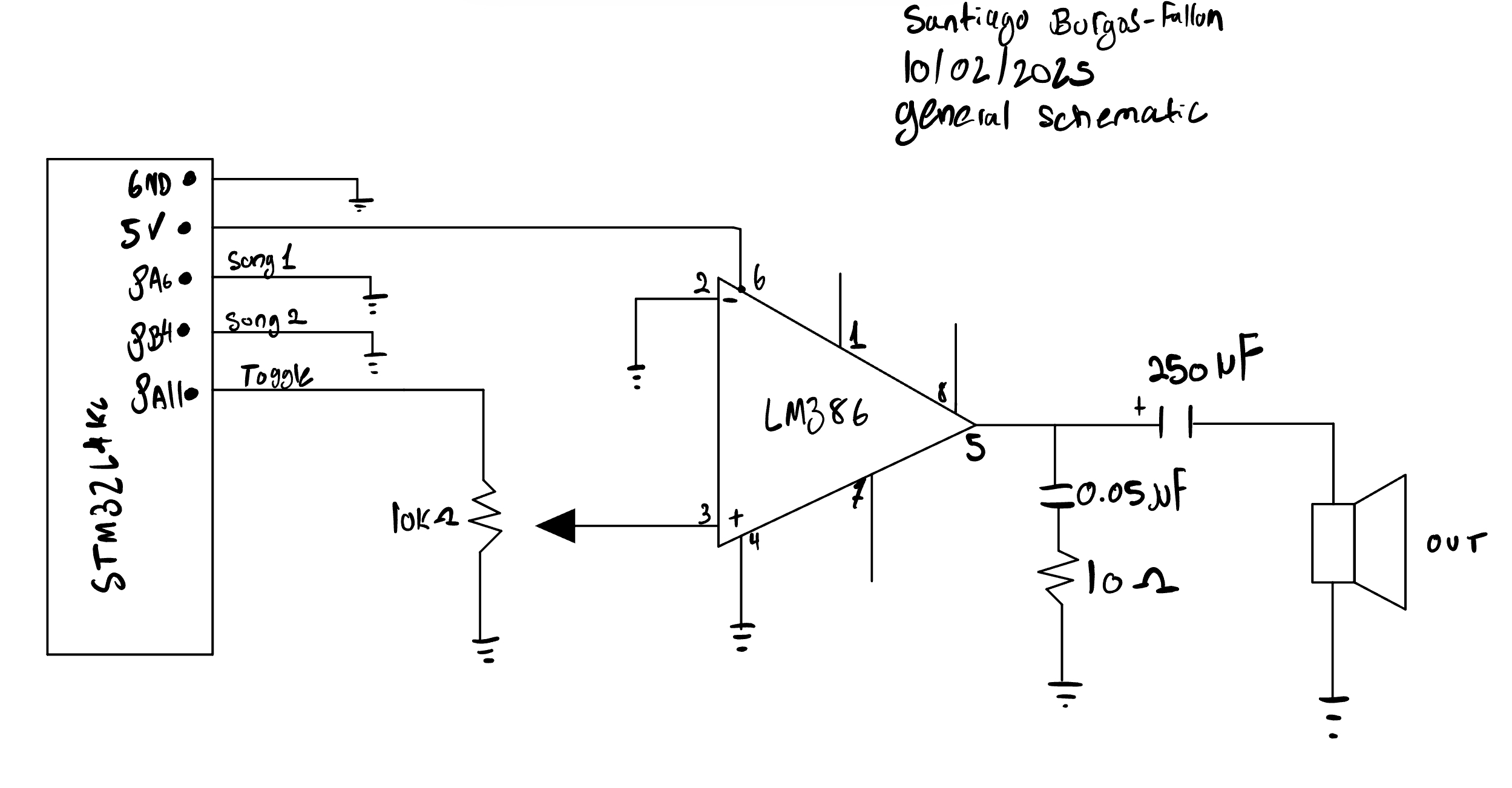
Pins used (hardware build): Audio out PA11 (GPIO to LM386 IN+ via pot/divider), START = PB4 (active-low to GND, internal pull-up), RESET = PA6 (active-low to GND, internal pull-up).
Hardware
LM386 minimum-parts hookup
- Input network:
- 10 kΩ potentiometer (recommended): MCU pin → pot top; pot bottom → GND; wiper → LM386 pin 3 (IN+) (volume).
- LM386 pins:
- Pin 3 (IN+): from pot wiper or divider node.
- Pin 2 (IN−) and Pin 4: GND.
- Pin 5 (OUT): → 220–250 µF electrolytic (+ toward LM386) → speaker +; speaker − → GND; add 0.047–0.05 µF from pin 5 → GND (stability).
- Pin 6 (V_S): +5…9 V with 0.1 µF (and 10 µF) decoupling to GND near the IC.
- Pins 1 & 8: open (gain ≈ 20).
- Pin 3 (IN+): from pot wiper or divider node.
Common ground: MCU GND, LM386 GND, and speaker − must be tied together.
Timing & Accuracy — Detailed Calculations (1 µs Timer Tick, TIM2 32-bit)
Assumptions:
TIM2 prescaled to 1 MHz (1 µs per count), upcount to ARR, toggle GPIO on each update (so each update = one half-period). Frequencies are produced by rounding the half-period; durations are produced by counting half-periods. TIM2 on STM32L432 is 32-bit.
Core Formulae
Half-period in microseconds for target frequency ( f ) (Hz): \[ T_{1/2} \;=\; \frac{1}{2f}\ \text{s} \;=\; \frac{500{,}000}{f}\ \text{µs} \]
Program auto-reload as: \[ ARR \;=\; \operatorname{round}(T_{1/2}) \;-\; 1 \]
Actual frequency (because timer quantizes in 1 µs steps): \[ f_{\text{actual}} \;=\; \frac{1}{2\,\bigl(ARR+1\bigr)\cdot1\ \text{µs}} \;=\; \frac{500{,}000}{ARR+1}\ \text{Hz} \]
Per-half-period rounding is at most ±0.5 µs. Over the full period (two half-periods), the relative pitch error is bounded by: \[ \left|\frac{\Delta f}{f}\right| \;\lesssim\; \frac{f}{10^{6}} \quad\text{(with 1 µs tick)} \]
At 1 kHz → ≤ 0.10 %; at 220 Hz → ≤ 0.022 % (≪ 1 %).
Theoretical Frequency Limits (Timer-Only)
Using 1 µs tick and a 32-bit auto-reload:
Minimum frequency largest half-period, \((ARR_{max}= 2^{32}-1)\): \[ T_{1/2,\max}=(ARR_{\max}+1)\cdot1\,\text{µs}=4{,}294{,}967{,}296\ \text{µs} =4{,}294.967296\ \text{s} \] Full period 8,589.934592 s. \[ \boxed{f_{\min}=\frac{1}{8{,}589.934592}\ \text{Hz}=\mathbf{0.0001164153\ Hz}} \] (period ≈ 2 h 23 m 10 s)
Maximum frequency (smallest half-period, (ARR=0)): \[ T_{1/2,\min}=1\,\text{µs}\;\Rightarrow\;T=2\,\text{µs},\qquad \boxed{f_{\max}=\mathbf{500{,}000\ Hz}} \]
Representative Notes — Actual Values (from round-to-µs)
| Target (f) (Hz) | (T_{1/2}) ideal (µs) → rounded | (ARR) | (f_{}) (Hz) | Error |
|---|---|---|---|---|
| 220.0 | 2272.727… → 2273 | 2272 | 219.9736 | −0.012 % |
| 329.6 | 1516.989… → 1517 | 1516 | 329.5979 | −0.00064 % |
| 440.0 | 1136.364… → 1136 | 1135 | 440.1408 | +0.032 % |
| 523.3 | 955.467… → 955 | 954 | 523.5602 | +0.050 % |
| 659.3 | 758.380… → 758 | 757 | 659.6306 | +0.050 % |
| 1000.0 | 500.000… → 500 | 499 | 1000.0000 | +0.000 % |
Frequency step size near a given (f) from a 1 µs half-period grid is approximately
(f ). Examples: at 1 kHz → ~2 Hz/step; at 220 Hz → ~0.097 Hz/step.
Duration Quantization (Notes): What it is, why it happens, and how big the error is
Model. Each note is played by executing an integer number of half-periods (one GPIO toggle per timer update).
Let the target frequency be (f) (Hz) and the requested duration be (d) (ms).
- Half-period (with a 1 µs timer tick): \[ T_{1/2} \;=\; \frac{1}{2f}\ \text{s} \;=\; \frac{500{,}000}{f}\ \mu\text{s} \]
- Ideal (real-valued) number of toggles: \[ N^* \;=\; \frac{2 f d}{1000} \]
- Implemented toggles (what code uses): (N=(N^*)) (nearest integer).
Actual time played: \[ t_{\text{actual}} \;=\; N\cdot T_{1/2} \]
Why quantization error occurs. Because (N) must be an integer, (N) can differ from \((N^*)\) by at most \((T_{1/2})\). Multiplying by \((T_{1/2})\) gives the worst-case time error: \[ \boxed{\,|\Delta t_{\text{note}}| \;\le\; \tfrac{1}{2}\,T_{1/2}\,} \]
Interpretation. - The step size of note duration is exactly \[(T_{1/2})\] (each additional toggle adds one half-period). - The largest absolute error happens at low frequencies \[(large (T_{1/2}))\], because the duration “grid” is coarser. - For a given requested duration (d) (e.g., 125 ms), the percent error bound is \[ \boxed{\,\%\text{error} \;\le\; \frac{T_{1/2}}{2\,d}\times 100\%\,} \]
Explicit values
( f = 220, ):
\[ T_{1/2} = \frac{500{,}000}{220} = 2272.727\,\mu\text{s} = \mathbf{2.273\,\text{ms}} \] \[ |\Delta t| \le \tfrac{1}{2}T_{1/2} = \mathbf{1.136\,\text{ms}} \] \[ \%\text{error} \le \frac{2.273}{2\cdot 125}\times 100\% = \mathbf{0.91\%} \]( f = 440, ):
\[ T_{1/2} = \frac{500{,}000}{440} = 1136.364\,\mu\text{s} = \mathbf{1.136\,\text{ms}} \] \[ |\Delta t| \le \mathbf{0.568\,\text{ms}} \] \[ \%\text{error} \le \frac{1.136}{2\cdot 125}\times 100\% = \mathbf{0.45\%} \]( f = 659.3, ):
\[ T_{1/2} = \frac{500{,}000}{659.3} = 758.380\,\mu\text{s} = \mathbf{0.758\,\text{ms}} \] \[ |\Delta t| \le \mathbf{0.379\,\text{ms}} \] \[ \%\text{error} \le \frac{0.758}{2\cdot 125}\times 100\% = \mathbf{0.30\%} \]( f = 1000, ):
\[ T_{1/2} = \frac{500{,}000}{1000} = 500.000\,\mu\text{s} = \mathbf{0.500\,\text{ms}} \] \[ |\Delta t| \le \mathbf{0.250\,\text{ms}} \] \[ \%\text{error} \le \frac{0.500}{2\cdot 125}\times 100\% = \mathbf{0.20\%} \]
Rests: handled by a 1 kHz “ms timer” → granularity 1 ms. Since your rest durations are already integers in ms, the rest error is 0 ms (within that 1 ms quantum).
Software-Polled Limitations (Practical Upper Bound)
I implement notes by polling TIM2’s update flag (UIF), then clearing UIF and toggling the GPIO. The timer can generate very fast updates, but to avoid missed toggles the CPU must service each update before the next half-period elapses.
Let
- \(f_{cpu}\) = core clock (e.g., 80 MHz)
- \(t_{service}\) = time for me to (1) detect UIF=1 and exit the loop, (2) clear
TIM2_SR, and (3) toggle the ODR bit (plus loop overhead)
To guarantee no misses I need the half-period to exceed my service time:
\[ T_{1/2} \;>\; t_{\text{service}} \quad\Longrightarrow\quad f_{\max,\text{service}} \;\approx\; \frac{1}{2\,t_{\text{service}}} \]
Concrete examples
\[t_{\text{service}} = 2.0,\mu\text{s}\] \[ f_{\max,\text{service}} \approx \frac{1}{2\cdot 2.0\,\mu\text{s}} = \mathbf{250\,\text{kHz}} \] \[t_{\text{service}} = 1.0,\mu\text{s}\] \[ f_{\max,\text{service}} \approx \frac{1}{2\cdot 1.0\,\mu\text{s}} = \mathbf{500\,\text{kHz}} \] \[t_{\text{service}} = 0.5,\mu\text{s}\] \[ f_{\max,\text{service}} \approx \frac{1}{2\cdot 0.5\,\mu\text{s}} = \mathbf{1.0\,\text{MHz}} \]
However, with my 1 µs timer tick, the timer itself caps the maximum frequency at
\[ f_{\max,\text{timer}} \;=\; \frac{1}{2\cdot 1\,\mu\text{s}} \;=\; \mathbf{500\,\text{kHz}} \]
So the true practical max is
\[ f_{\max} \;=\; \min\!\bigl(f_{\max,\text{service}},\, f_{\max,\text{timer}}\bigr) \]
In other words:
- If \(t_{service}\) > 1s → software-limited below 500 kHz
- If \(t_{service}\) < 1s → timer-limited at 500 kHz
Either way, this is orders of magnitude above audio. My Für Elise range (220–1319 Hz) is tiny compared to even a conservative software-limited few-hundred-kHz ceiling.
Compliance Statement (from these calculations)
- Pitch accuracy (220–1000 Hz): worst-case rounding ≤ 0.10 % @1 kHz and ≤ 0.022 % @220 Hz → meets ±1 % spec with wide margin.
- Durations: note-length error ≤ ½ (T_{1/2}) (≤ 0.25–1.14 ms across 1 kHz–220 Hz for 125 ms notes); rests at 1 ms resolution → tempo is within ~1 % worst case, typically ≪ 1 %.
- Range: timer math supports (f) from 0.000116 Hz up to 500 kHz; software-service considerations are still far above the audio range used here.
Schematic
Writeup / Summary (General Specs)
- Meets requirements? Yes.
- Time spent: 6 hours.
- AI prototype: attempted; reflection below.
Verification & Bring-Up
- Functional checks
- Rests (f = 0) produce silence for specified ms.
- End marker (duration = 0) terminates playback cleanly.
- START (PB4) gates initial playback; RESET (PA6) aborts mid-note.
- Rests (f = 0) produce silence for specified ms.
- Debugging approach
- Added debug watches for computed ( ARR ), half-period, and toggle counts.
- Used run + hit-count breakpoints (not single-step), since stepping halts the timer and audio.
- LED telemetry for “in-note vs rest” helps confirm tempo without a scope.
- Added debug watches for computed ( ARR ), half-period, and toggle counts.
AI Prototype & Reflection
Prompt used
NoteLLM Prompt
What timers should I use on the STM32L432KC to generate frequencies ranging from 220 Hz to 1 kHz? What’s the best choice of timer if I want to easily connect it to a GPIO pin? What formulae are relevant, and what registers need to be set to configure them properly?
Reflection
- Quality & speed: The LLM quickly identified a general-purpose timer (TIM2/TIM3), the key equations \[ f = \frac{f_{\text{TIM}}}{(PSC+1)(ARR+1)},\qquad ARR \approx \frac{f_{\text{TIM}}}{f(PSC+1)}-1 \] and discussed PWM vs. toggle-on-update. It was faster than manual document search when I couldn’t recall register names.
- With datasheet attached: Accuracy improved—calling out that TIM2 is 32-bit on L4 and lives on APB1 helped bound ranges and justify a 1 MHz tick.
- Compared to my approach: I chose toggle-on-update to guarantee 50% duty without CCR/PWM setup (simpler for an LM386 square-wave input).
- LLM as doc search: Helpful for where to look and order of operations (RCC → GPIO → TIM), while I still verified addresses/bitfields in the reference manual.
- Tips that worked: Specify the target tick (e.g., “make TIM2 1 MHz”), request the exact init sequence, and state pin constraints so it doesn’t assume PWM unless I want it.
Conclusions
The design satisfies the lab requirements:
- Plays Für Elise at the specified tempo with accurate pitches and rests.
- Uses bare-metal register macros; no CMSIS.
- Timing math demonstrates ≤ 0.1% typical pitch error (≪ 1%) in 220–1000 Hz.
- The LM386 stage is correctly biased and decoupled; the MCU never drives the speaker directly.
Time spent: 6 hours.
Future work: add a second composition; experiment with PWM+CCR for variable duty or an RC-filtered DAC for softer timbre.